
This explains how to use cutting plotter driver options. Available from 26.10 onwards.
The contour cutting function allows you to define cutting paths for workflows where the design is printed and subsequently cut using a cutting plotter.
The contour cutting configuration is available from the Properties panel under Contour Selection.
The main options include:
Import cut elements
Registration marks
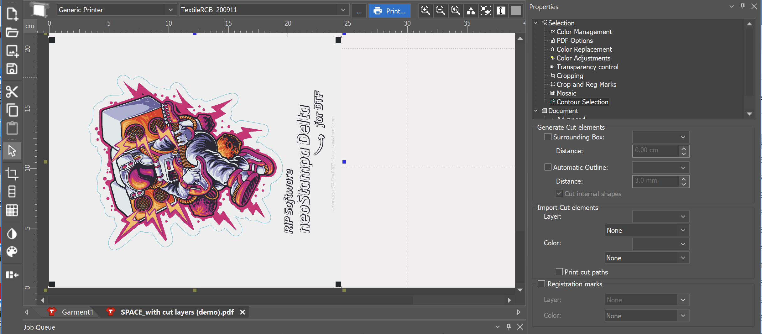
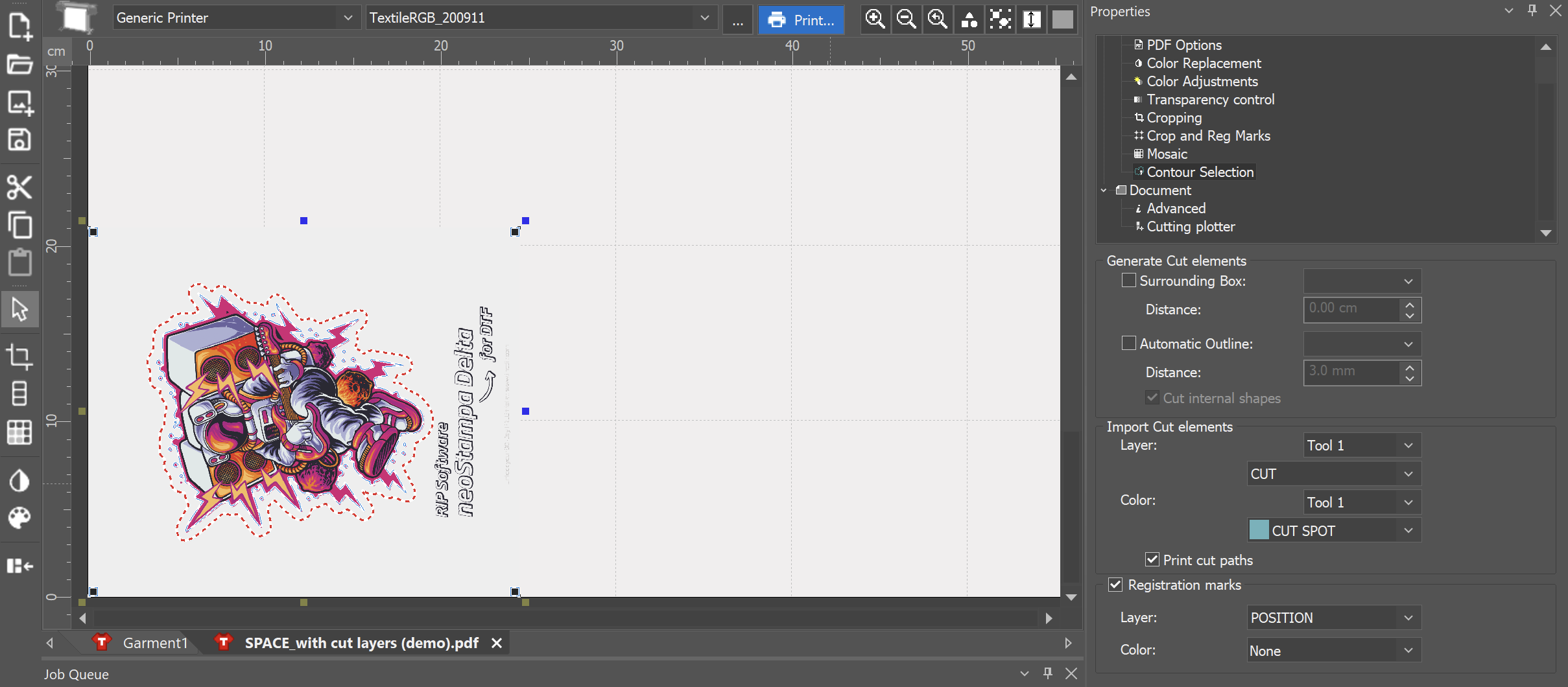
Contour Cut Elements & Registration Marks
neoStampa can detect cutting elements and registration marks included in the imported document.
Cutting paths can be identified using layers and spot colors defined in the source file.
When a cutting color is selected, the corresponding paths are displayed as dotted lines in the document preview, indicating that they will be used as cutting paths.
The Print cut paths option allows the selected paths to be both printed and used for cutting.
Save the Print & Cut Configuration
Print and cutting configurations are saved as a CP5 print document. The CP5 format replaces the previous CT5 cutting file workflow and stores the complete print document configuration, allowing the job to be reopened with its settings. The CP5 document can preserve information such as:
Source file selection
Cutting path selection
Registration mark configuration
Cutting plotter selection and settings
Printer and scheme selection
Print document layout and configuration
Other document-specific print and cutting settings
This allows the complete Print & Cut job configuration to be saved and reopened without having to configure the cutting paths, registration marks, plotter, and other document settings again.
Note: The previous CT5 format was used to export cutting paths for CiberCut. This workflow has been replaced by the CP5 print document format, which stores the complete document configuration rather than only the cutting information.
Open a CP5 Document
To reuse a saved Print & Cut configuration, open the CP5 document in neoStampa.
The document restores the saved configuration, including the source file and its associated print and cutting settings.
CP5 files must be opened using the Open command in neoStampa. Drag-and-drop is not supported for CP5 documents.
Previous Version
This program function allows us to create a cutting path for those printers that support contour cuts (Print & Cut) or for plotters with a cutting system. We access the option from the Properties.
The options for the creation of the contour are:
- Contour cut elements
- Registration marks
- Cut the surrounding box
Contour cut elements & Registration marks
The program interprets the design and locates all cut elements and registration marks as layers in a PDF document.
The elements' colors must be spot colors.

When choosing a color from the list, you can see on the screen that the fillets with that particular color are seen as a dotted line. This shows that it is a cutting line. In this image, you can see an outside cutting outline.
The option 'Print cut paths' offers the possibility that the stroke can be printed and cut. In this case, both the original color fillet and thickness and the dotted line will be shown. The PostScript clip paths option allows the cutting of areas of image trimming generated directly in Photoshop®. Consult the Adobe Photoshop® manual to know about how to generate layouts in a document and include them in a Photoshop EPS together with the image.
Cut surrounding box
This creates a rectangle outside the limits of the design, both for images and vectorial designs. With this option, we can introduce the distance between the contour that will be created, and the rectangle marking the limits of the design.
Send Directly to Cutting Plotter
Once generated the cropping path, it is possible to send it to a cutting plotter. By clicking on the 'Cut...' button you will access the configuration window for the Contour cutting:
In Plotter, you will be able to select the model of the plotter you will use. To add plotters to the list or configure your connexions, press 'Configure...'.
Depending on the model of the plotter selected, it will be possible to control directly the cutting speed as well as its pressure and acceleration. It is also possible to select the cutting quality when bends are being cut in the section Curve resolution. The option Read registration marks will only be active in the plotters in which the reading of these marks is activated through software, that is, the program has to indicate the plotter to search for the register marks in order to position itself correctly in the origin of the printing. The Plotter options button opens the next window with Advanced options.
Axes
In all plotters that allow configuration, you should select the option of rotating 90° the axes, in order to adjust the printing and cut, the origin of coordinates is to be found to the right of the plotter. For plotters that do not have the function of reading register marks (OPOS), we recommend using the register marks from the previous branch in the Control Center, which only prints angles. Place the cut origin on the right mark, once the material has been loaded in the cutting plotter.

Export Paths
All the cutting plots that we may create can be exported to be cut with the CiberCut software, special for vinyl cutting. Pressing the button Export Paths, the file selection window will pop up, and it will allow you to enter a file name and select where to save it. The generated file has the extension "ct5" and it is only valid to be loaded in the program CiberCut. This contains the cutting pathway of the design and the exact position so that when cut, it will match the printed image if register marks are used (OPOS).